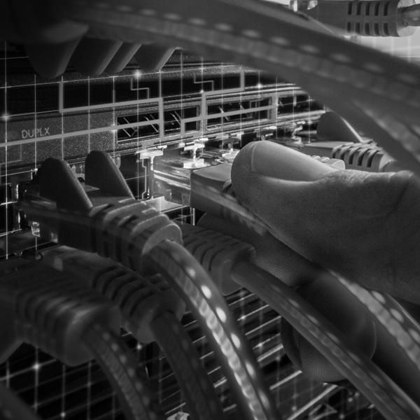
At present, when programming Programmable Logic Controllers (PLCs), if the equipment is not physically available, simulation software such as PLCSim or OpenPLC can be used. These are capable of importing the code created in the manufacturer's "IDE'' and emulating the behavior of the PLC. The versatility of these simulators will allow to exemplify most of the functions that the controllers have. But when simulating industrial networks these softwares are quite poor or lack such functionality. It is true that there are solutions that could approach reality, creating virtual machines with NodeRED and VirtualmakTCP or even with TIA Portal in the case of Siemens. However, in offensive practices where we have to analyze open source and proprietary communication protocols, or even different firmware versions in the same device, it is essential to have the physical equipment.
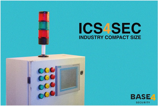
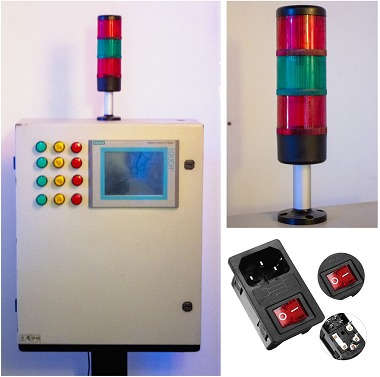
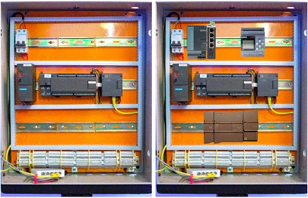
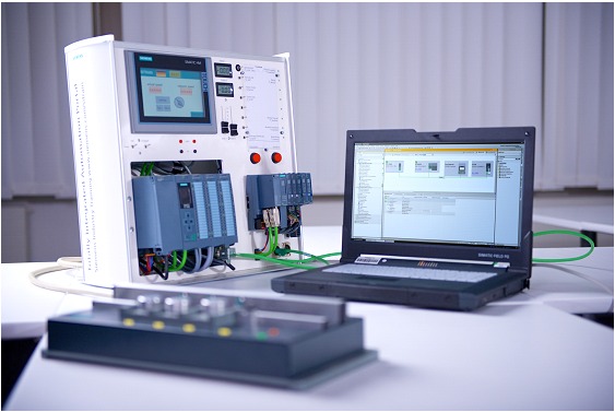
This post describes the design and construction of a low-cost educational board at an early stage, oriented to Siemens products and based on the standards of their exams to perform offensive practices. The equipment built at the date of publication of this post has 12 indicator lights that can be used to indicate the status of the control outputs, an "industrial traffic light" style beacon, a Human Machine Interface (HMI) system, a Siemens S7-200 with its Ethernet adapter module and a switch. A terminal block with 48 extra connectors for future upgrades is also included, and there is enough room to add more devices.
Introduction
For several years, the development of process control has led to the development of production tasks based on automation systems. For which in many occasions it is necessary a study, where prototypes are developed prior to the construction of a real system.
In these prototypes, the main process parameters of interest, such as temperatures, pressures, levels, flows, concentrations, etc., are continuously monitored. These values can be adjusted so that the tasks are performed automatically, turning on valves, pumps, heaters, motors, relays, among others.
This performed within a laboratory in an educational environment, taken to a security context will allow students to not only broaden their experience in designing, building and monitoring equipment, but also how to secure, upgrade and protect it.
On the other hand, it is possible to connect the board to industrial simulation software to see the results in a didactic way without having to build a prototype in the garden of our homes or incur expenses.
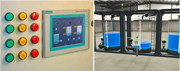
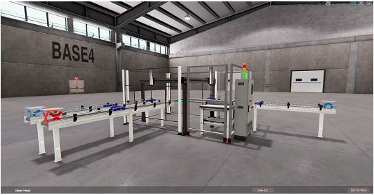
Let's suppose an example: A student, after "listening" to the communication protocol, manages to keep a session started and change the state of one of the PLC outputs. Let's imagine that in a real implementation that output corresponds to a valve that pours liquids into a tank. Imagining it is easy, but "seeing" it creates a real sense of the danger of such a state change and we can appreciate it thanks to simulators such as Factory I/O or Machine Simulator.
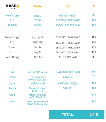
Many of these devices can be obtained second hand at almost 50% of their value (this is only useful for educational environments, since these devices guarantee a correct operation within a period of time imposed by the manufacturer, using them outside these margins in a real industrial environment would not comply with safety standards).
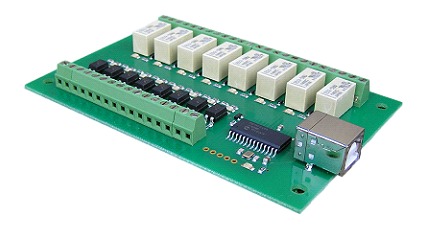
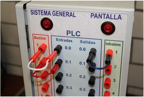
The design of the unit was made in such a way that the different digital input and output signals are available on connection terminals inside the cabinet. In this way the student is able to propose different configurations of operation of the equipment in a simple and fast way.
Design and Construction
In order to facilitate the explanation of the design and construction of the equipment, it was divided into three fundamental blocks: Door, cabinet and interior. These are described below.
Door
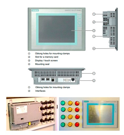
As mentioned above, the equipment was built using a metal cabinet. This has in its front part a door with the equipment and necessary components, 12 22 mm indicator lights that use 24 volts of direct current to operate, with which you can indicate states or stages in a control sequence. Siemens mp 277 touch of 8 inches was also incorporated. In a next stage, 16 push buttons will be added to simulate actuators.
A good starting point to obtain the necessary knowledge before starting our research can be the official Siemens exams, as they offer step-by-step manuals detailing the wiring, protocols, software, etc. Part of this project was born with the idea of replicating the SITRAINtraining stations.
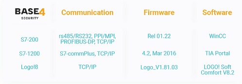
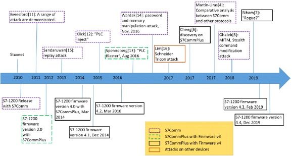
Both models and firmware versions were chosen based on a list of known vulnerabilities, for more technical details I invite you to read this POST where a real attack is technically addressed. As a reference in the following diagram we can see a timeline where product releases, exploits and firmware patches are located.
We explained in this post the design and construction at an early stage of a didactic support equipment for offensive practices on Programmable Logic Controllers, their protocols and software. It could be considered a great investment for individuals, educational environments, or for complete Red Team/Blue Team teams to develop solutions for their customers.
Although the construction of the equipment is still in process in a first stage was able to deliver satisfactory results, the reduced cost compared to other solutions and the practicality it brings along with the simulators gives a competitive advantage when undertaking an OT solution, and not only meets the need for safety practices or programming, but could also correct entire production lines making them more efficient just by simulating them, from the comfort of our homes.
References and Bibliography

